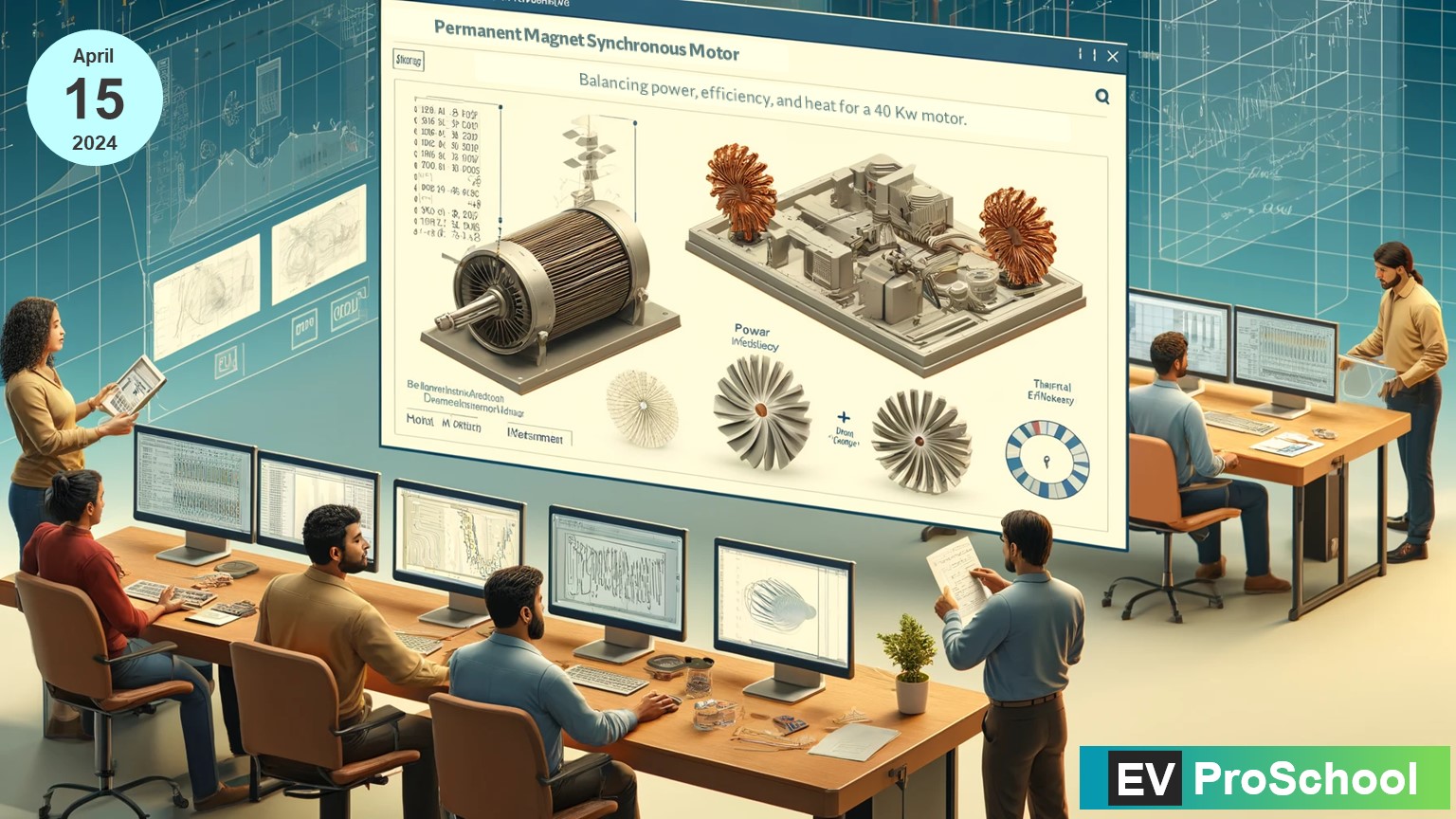
In the realm of electric motors, particularly Permanent Magnet Synchronous Motors (PMSMs), achieving an optimal balance between power output, energy consumption, and heat generation represents a pinnacle of engineering excellence. PMSMs are renowned for their efficiency and performance in a wide array of applications, from electric vehicles (EVs) to industrial machinery. However, refining their electromagnetic designs is crucial for pushing the boundaries of what these motors can achieve. This blog post explores strategies for optimizing PMSM motors, ensuring they deliver maximum power with minimal energy wastage and heat production.
Understanding PMSM Motor Design
A PMSM motor operates on the principle of electromagnetic interaction between the rotor’s permanent magnets and the stator’s winding currents. The design challenges in PMSMs primarily revolve around maximizing the magnetic flux density while minimizing losses that contribute to heat generation.
Key Design Parameters
- Magnet Material: The choice of magnet material affects the motor’s efficiency and thermal characteristics. Rare-earth magnets, such as neodymium, offer high magnetic flux density but at a higher cost and with more sensitivity to heat.
| Magnet Material | Characteristics | Temperature Range | Applications |
|---|---|---|---|
| Neodymium Iron Boron (NdFeB) | High magnetic strength, available in grades N through EH. EH grade works best at elevated temperatures up to 200°C. | Up to 200°C for EH grade | Room temperature motor applications, sensors, electronics |
| Samarium Cobalt (SmCo) | High operating temperature and low risk of demagnetization. UHT grade can operate at up to 550°C. | Up to 550°C for UHT grade | Guidance systems, gyroscopes, traveling wave tubes, medical instrumentation |
| Aluminum Nickel Cobalt (Alnico) | Mechanically strongest material. | – | Used where strong permanent magnets are required |
| Ferrite (Ceramic) | Low cost, but lower energy product compared to others. | – | Cost-effective applications requiring permanent magnets |
| Soft Magnetic Composite (SMC) | Thermally isotropic, low eddy current loss, magnetically isotropic allowing for 3D flux paths. | – | High-performance motors requiring 3D flux paths |
The selection of the right magnet material for an electric motor design involves trade-offs between various factors such as temperature range, magnetic strength, resistance to demagnetization, cost, and the specific application requirements.
- Stator Winding Configuration: The stator’s winding pattern significantly impacts the motor’s electromagnetic efficiency. Optimizing the winding configuration can enhance torque production and reduce losses.
| Winding Configuration | Advantages | Application Focus |
|---|---|---|
| Hairpin Windings | Increased power density, maximized slot-filling factor, lower DC copper losses | Electric Vehicle Motors, High-reliability motor drives |
| Single-Layer Full-Pitched (SF) Windings | Improved average torque, reduced torque ripple | Constant torque range in dual three-phase IPM machines |
| Double-Layer Short-Pitched (DS) Windings | Better torque performance | Constant power range, performance under one winding set excitation |
| Lap Windings | Higher current-carrying capacity, improved cooling efficiency, enhanced commutation | Industrial machinery, Electric Vehicles, Renewable Energy Systems |
These winding configurations are used to match specific performance requirements and to improve efficiency in electric motors used across a variety of applications, from electric vehicles to industrial machines. Each configuration offers unique benefits, so the selection would depend on the specific application needs and the desired motor characteristics.
- Rotor Geometry: The shape and size of the rotor influence the motor’s magnetic circuit, affecting its power output and efficiency.
Strategies for Electromagnetic Design Refinement
Advanced Simulation Tools
Leveraging advanced electromagnetic simulation software allows engineers to model and analyze the motor’s design before physical prototyping. These tools can simulate various operating conditions, providing insights into how different design modifications impact performance, efficiency, and heat generation.
Here’s a list of advanced electromagnetic simulation software, their providers, and some details about them:
| Software | Provider | Features | Tentative Cost |
|---|---|---|---|
| Ansys Maxwell | Ansys | Specialized in low-frequency EM field simulation for electric machines, transformers, and other devices. Offers advanced magnetic modeling and multiphysics couplings. | Contact Ansys for a quote. |
| EMWorks2D | EMWorks | 2D electromagnetic field simulation software ideal for electric motor design with parametric simulation capabilities. | Free trial available; contact EMWorks for full version pricing. |
| Simcenter MAGNET | Siemens | Focused on low-frequency electromagnetic field simulations, including advanced electromagnetic material modeling and electromagnetic-motion simulation. | Contact Siemens for a quote. |
| COMSOL Multiphysics | COMSOL | Features built-in tools to model coils and perform electromagnetic stress, force, and torque calculations. Suitable for a wide range of multiphysics simulations. | Contact COMSOL for a quote. |
| MotorWizard | EMWorks | Electric motor design software that allows for quick performance prediction and includes an extensive material library. | Free trial available; contact EMWorks for full version pricing. |
Please note that the costs of these software packages are not typically publicly disclosed and can vary greatly depending on the specific needs of the user, such as licensing options, the number of seats, additional modules, and the level of customer support. It’s recommended to contact the software providers directly for the most accurate and up-to-date pricing information.
Thermal Management
Effective thermal management is paramount in PMSM design. Incorporating materials with high thermal conductivity, designing efficient cooling systems, and optimizing the motor structure for heat dissipation can significantly reduce thermal stresses and improve longevity.
| Type of Loss | Description | Causes of Heat Generation |
|---|---|---|
| Copper Loss | Electrical resistance in the windings | Current flowing through the resistive copper windings generates heat (I²R losses). |
| Iron Loss | Magnetic losses in the motor core | Includes hysteresis loss (due to magnetic field reversals in the core material) and eddy current loss (induced currents within the core material). |
| Mechanical Loss | Friction and windage | Bearings, brushes (if applicable), and air resistance can generate heat due to friction and the motor’s moving parts. |
| Stray Load Loss | Non-ideal distributions of magnetic fields | Harmonics and parasitic currents that are not accounted for in the ideal motor model can lead to additional heat generation. |
| Core Loss | Alternating magnetic flux in the core | It’s part of iron losses and is specifically due to alternating flux causing minor hysteresis and eddy currents in the stator core. |
Each of these loss types contributes to the overall thermal profile of the motor. Effective thermal management is crucial for maintaining motor efficiency and longevity, which involves materials with high thermal conductivity, efficient cooling systems, and motor structures optimized for heat dissipation.
Optimization of Magnet Placement
The placement of permanent magnets on the rotor can be optimized to reduce cogging torque and minimize eddy current losses. Strategic magnet placement can also enhance the motor’s back-EMF waveform, leading to better control characteristics and efficiency.
Strategically placing permanent magnets in a rotor can significantly minimize cogging torque and eddy current losses. Research suggests utilizing arc-shaped triangular magnets, and methods like “hybrid skew” where magnets with different shapes for North and South poles are used. Grouping magnets and adopting configurations like short-pitched and skewed magnets also prove effective. Additionally, adjusting stator configurations can contribute to reductions in cogging torque. These optimizations involve the use of software tools like Finite Element Analysis for evaluation and are validated through experimental prototyping and testing.
Achieving the Optimal Balance
The journey to refine electromagnetic designs in PMSM motors is a meticulous process of iteration and innovation. By focusing on the key areas of material selection, design optimization, thermal management, and harmonic reduction, engineers can significantly enhance the motor’s performance. The goal is to achieve a motor that not only delivers high power output and efficiency but also operates reliably within its thermal limits.

Harmonic Reduction
Harmonics in the motor’s electromagnetic field can lead to increased losses and heat generation. Employing techniques such as skewing the stator slots or using fractional slot windings can reduce harmonics and improve the motor’s overall performance.
Material Innovation
Research into new materials and manufacturing techniques can yield significant benefits. For example, soft magnetic composite materials offer reduced eddy current losses at high frequencies, while advanced insulation materials can minimize electrical losses in the windings.
Conclusion
As the demand for more efficient and powerful electric motors continues to rise, the importance of refining electromagnetic designs in PMSMs cannot be overstated. Through strategic design improvements and the use of cutting-edge materials and technologies, it’s possible to achieve an optimal balance between power output, energy consumption, and heat generation. This not only advances the capabilities of PMSM motors but also contributes to the broader goal of sustainable and efficient electric power for the future.


