The inverter switching frequency in electric motors, particularly in applications like electric vehicles (EVs) or industrial machinery, plays a crucial role in determining the efficiency, performance, and overall reliability of the system. Here’s an overview of how the inverter switching frequency is decided, controlled, and what happens during its operation, explained step by step:
Step 1: Understanding Inverter Switching Frequency
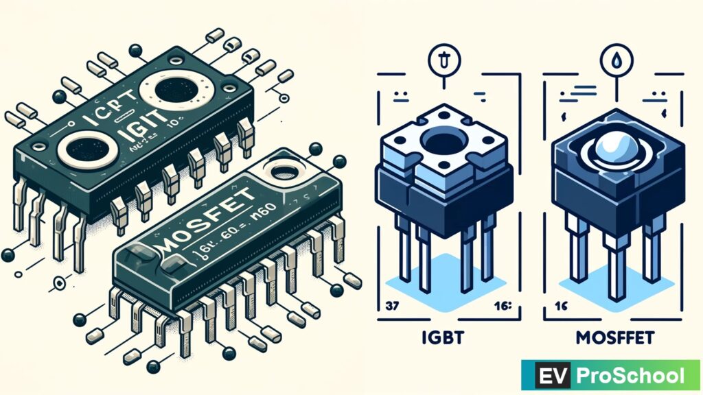
The inverter switching frequency refers to the rate at which power electronic switches, such as Insulated Gate Bipolar Transistors (IGBTs) or Metal-Oxide-Semiconductor Field-Effect Transistors (MOSFETs), cycle on and off. This frequency is critical in the conversion process from DC (direct current) to AC (alternating current) to efficiently drive electric motors. High-frequency switching can result in more efficient operation and smoother output waveforms, but also leads to increased heat generation and potential electromagnetic interference.
A) Difference between IGBTs and MOSFETs:
| Feature | IGBT | MOSFET |
|---|---|---|
| Conduction Type | Bipolar (carriers are both electrons and holes) | Unipolar (carriers are primarily electrons) |
| Voltage Rating | Higher (up to several kV) | Lower (up to a few hundred V) |
| Current Rating | Higher | Lower |
| Switching Speed | Slower than MOSFETs | Faster than IGBTs |
| Efficiency | Less efficient at lower voltages | More efficient at lower voltages |
| Applications | Suitable for high voltage applications | Preferred for low to medium power applications |
| Cost | Generally more expensive | Generally less expensive |
B) Selection of IGBT or MOSFET based on inverter requirements:
- Power Requirements: For high power applications (e.g., electric vehicle drive trains), IGBTs are often preferred due to their ability to handle higher voltages and currents. MOSFETs are more suitable for lower power applications (e.g., consumer electronics).
- Switching Frequency: MOSFETs are better suited for higher switching frequencies due to their faster switching speeds, which reduces losses and improves efficiency in applications where high switching frequencies are beneficial.
- Efficiency and Heat Management: At lower voltages, MOSFETs are more efficient and generate less heat compared to IGBTs, making them more suitable for applications where thermal management is a concern.
C) Limitations and Comparison:
| Feature | IGBT Limitations | MOSFET Limitations |
|---|---|---|
| Voltage Rating | Less efficient at low voltages | Voltage limitations restrict high power use |
| Switching Speed | Slower switching can lead to higher losses | Very high switching speeds can increase EMI |
| Cost | Cost may be prohibitive for low power systems | Higher cost for high voltage, high power models |
| Heat Dissipation | Requires substantial heat management systems | Generally has better thermal performance |
| Complexity | Complex driving circuitry required | Simpler to drive but requires careful handling |
Graph: Efficiency vs. Frequency for IGBTs and MOSFETs
Let’s plot a hypothetical graph comparing the efficiency of IGBTs and MOSFETs as a function of switching frequency. This graph will illustrate how the efficiency tends to decrease with frequency due to increased switching losses but shows that MOSFETs maintain higher efficiency at increased frequencies compared to IGBTs.

Here’s a hypothetical graph showing the efficiency versus switching frequency for IGBTs and MOSFETs. As depicted, both types of switches experience a decline in efficiency as the frequency increases due to greater switching losses. However, MOSFETs maintain a higher efficiency compared to IGBTs at increased frequencies, which aligns with their suitability for applications requiring higher switching speeds and better thermal performance. This visualization helps in understanding how different applications may benefit from selecting the appropriate type of power electronic switch.
Step 2: Deciding the Switching Frequency
- Performance Requirements: The desired performance of the motor (such as torque and speed characteristics) and the specific application (EV, industrial, etc.) influence the choice of switching frequency. Higher frequencies can achieve smoother motor operation and better performance but at the cost of increased heat and losses.
- Thermal Management: The ability of the system to dissipate heat generated by the switching process is a critical factor. Higher switching frequencies generate more heat, requiring more robust cooling solutions.
- Efficiency Considerations: The efficiency of the motor and inverter system is affected by the switching frequency. While higher frequencies can reduce certain losses (like torque ripple), they increase others (like switching losses).
- Electromagnetic Interference (EMI): Higher switching frequencies can lead to increased electromagnetic interference, impacting other electronic systems. Shielding and filtering strategies must be considered.
- Component Specifications: The characteristics of the switching components (IGBTs, MOSFETs) such as maximum switching speed, power ratings, and efficiency at various frequencies also dictate the feasible switching frequency range.

Step 3: Controlling the Switching Frequency
The switching frequency of inverters in electric motor applications is critically controlled to optimize performance, efficiency, and minimize noise and wear. Several key technologies are employed to manage these frequencies effectively:
1) DSP: Digital Signal Processor
A Digital Signal Processor (DSP) is crucial for managing and manipulating the digital signals used to control the switching actions of inverters. DSPs are highly efficient at processing data in real-time, which is essential for dynamic and responsive motor control. They adjust the switching frequency based on inputs from various sensors and the desired motor output, ensuring optimal performance across different operating conditions.
2) PWM: Pulse Width Modulation
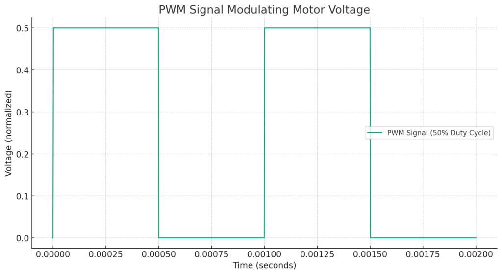
Pulse Width Modulation (PWM) is a method used to control the amount of power delivered to an electric load by breaking up the power into discrete on/off periods. The duty cycle of these pulses, which represents the proportion of time the signal is high versus low, controls the average voltage and current flowing to the motor. PWM is a crucial technique in controlling motor speed and torque while improving overall efficiency and reducing heat generation.
Graph: Effect of PWM on Motor Voltage and Current
To illustrate these concepts, let’s create graph to show how PWM affects motor voltage and current.

Here’s a graph representing a PWM signal with a 50% duty cycle at a frequency of 1 kHz. This waveform illustrates how the voltage applied to a motor is modulated: the signal alternates between on (high) and off (low) states. The duty cycle—50% in this case—indicates that the voltage is applied for half the time period, effectively controlling the average power supplied to the motor.
3) Feedback Loops
Feedback loops are essential in any control system to ensure stability and desired performance. In motor control, sensors monitor outputs such as speed, torque, and temperature, providing real-time data back to the controller (usually a DSP). This information is used to adjust the PWM signals dynamically, optimizing the motor’s performance according to the set parameters or desired outcomes.
What Happens During Operation
- Switching Action: The inverter switches rapidly turn on and off, creating a series of pulses that approximate an AC waveform to drive the motor.
- Motor Response: The motor responds to the synthesized AC waveform, with its speed and torque depending on the characteristics of the waveform (frequency, amplitude).
- Heat Generation: The rapid switching generates heat due to losses in the switching devices and the conducting wires. Efficient heat dissipation mechanisms are essential to prevent overheating.
- EMI Production: The switching action produces electromagnetic interference, which can affect nearby electronic devices. EMI mitigation strategies are employed to minimize these effects.
Conclusion
Deciding and controlling the inverter switching frequency is a balance between achieving desired motor performance, managing system efficiency, and dealing with practical limitations like heat dissipation, component specifications, and EMI. Through careful design, simulation, and testing, engineers can optimize the switching frequency to meet the specific needs of each application, ensuring reliable and efficient operation of the electric motor system.


